Difference between revisions of "Quick Start Guide"
(→First Print) |
(→Printrun (Pronterface)) |
||
| Line 42: | Line 42: | ||
:X and Y manual feed rate to 6000 | :X and Y manual feed rate to 6000 | ||
:Z manual feed rate to 200 | :Z manual feed rate to 200 | ||
| + | :E manual feed rate to 100 | ||
:Width, Depth and Height to 600 | :Width, Depth and Height to 600 | ||
:Click OK then restart Pronterface for the changes to take affect | :Click OK then restart Pronterface for the changes to take affect | ||
| Line 47: | Line 48: | ||
:In Pronterface click on the 'Connect' button at the top left of the main screen | :In Pronterface click on the 'Connect' button at the top left of the main screen | ||
:Once connected the dialog box on the right side of the screen should say 'Printer now online' | :Once connected the dialog box on the right side of the screen should say 'Printer now online' | ||
| + | :On the left side of the screen near the Check Temperature button activate the "Watch" check box | ||
:In the Pronterface control panel click on the +x 10 button to move the print head to the right 10mm | :In the Pronterface control panel click on the +x 10 button to move the print head to the right 10mm | ||
:Note: Calibrate the bed using the below instructions before moving the Z axis | :Note: Calibrate the bed using the below instructions before moving the Z axis | ||
Revision as of 20:37, 16 July 2014
Skip the background, just step me through it
THIS IS A WORK IN PROGRESS
Contents
Background
A 3D printer takes a 3D model and turns in into a plastic part. To do this there are a number of pieces of software complete this task. A good source of more information can be found here:Software Toolchain (reprap.org)) We suggest the following open source applications:
Section 1- Install software
Gigabot is fully compatible with open source programming tools supported by the RepRap community. We encourage you to become an active participant in this thriving community!
- There are two software programs required for printing with Gigabot.
USB to Serial driver
The Virtual Communications Port driver talks to your USB port in a way that Gigabot understands.
- Download and install the VCP driver for your specific operating system.
- Windows version setup executable.
- All operating systems.
- You may need administrator rights, or need to right click and "Run as Administrator".
Slic3r
Slic3r takes a 3D model (usually an .stl file) and turns it into G-code. G-code is the instructions for the 3D printer to create the part. A more detailed understanding of G-code can be found here.
- Download and install Slic3r.
- Read the complete Slic3r manual
- Download Slic3r settings File:Gigabot Slic3r config.ini to your local computer.
- Open Slic3r and go to File -> Preferences -> Mode -> Expert
- Click OK and follow prompt to restart Slic3r
- Once you have restarted Slic3r go to File -> Load Configuration
- Choose the Gigabot_Slic3r_config.ini configuration file you saved earlier
Printrun (Pronterface)
This program is the interface you will use to communicate with Gigabot. Once the 3D model (.stl) has been turned into G-code, it must be feed into the printer. This can be done by loading the G-code file onto a micro SD card and inserting it into Gigabot's Viki controller or feeding it from your computer to Gigabot via Pronterface. More information on Pronterface can be found Here
- Download and install Printrun for Windows or Mac.
- Open Pronterface and go to Settings -> Options
- Under the Printer Settings tab change:
- Baud rate to 250000
- Bed temp for PLA to 65
- Extruder temp for PLA to 195
- X and Y manual feed rate to 6000
- Z manual feed rate to 200
- E manual feed rate to 100
- Width, Depth and Height to 600
- Click OK then restart Pronterface for the changes to take affect
- With Gigabot turned on, plug the USB cable into your computer
- In Pronterface click on the 'Connect' button at the top left of the main screen
- Once connected the dialog box on the right side of the screen should say 'Printer now online'
- On the left side of the screen near the Check Temperature button activate the "Watch" check box
- In the Pronterface control panel click on the +x 10 button to move the print head to the right 10mm
- Note: Calibrate the bed using the below instructions before moving the Z axis
Section 2- Calibrating your Gigabot
Correct calibration will ensure the machine moves freely and in a precise manner. Investing some time with the calibration and your prints will turn out much better.
Belt Tension
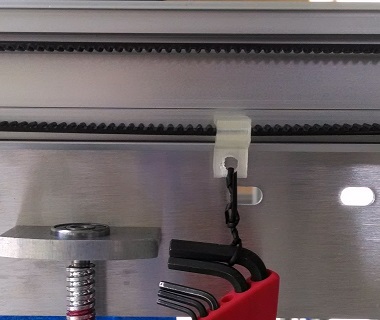
Ensure the proper belt tension for the two Y axis belts and the one X axis belt. If the belts are too loose the accuracy and surface finish of your part will suffer. Belts too tight will cause accelerated wear and reduce the life of your machine. Using the belt tension clip, supplied allen wrench set and a piece of string to hang the allen wrench set on the belt.
- If the belt is too loose it will look like this below:

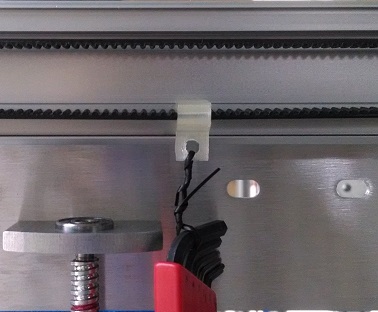
- If the belt has the proper tension it will look like this below:

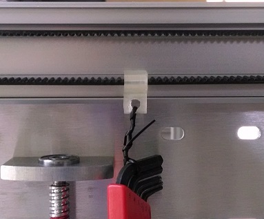
- If the belt is too tight it will look like this below:

Wheel Tension
Ensure the proper V-groove wheel adjustment for smooth operation. If the wheels are too loose the accuracy and surface finish of your part will suffer. Wheels too tight will cause undue stress on the motors and belts and reduce the life of your machine.
X and Y axis Wheels
- Using the supplied 8mm combination wrench and allen wrench
- Tighten the M5 nut fixing the wheel
- Loosen M5 nut 1/4 turn
- Adjust wheel tension by rotating the eccentric wheel spacer in a clockwise direction (when facing the head of the M5 bolt)
- Wheel should be just touching the aluminum bearing surface
- Tighten the M5 nut fixing the wheel
- Check there is no gap between the wheel and the bearing surface
- Check that wheel is not too tight and you can spin the wheel by hand
Z axis Wheels
- The two wheels on the back of the bed side plates should be touching the Z axis uprights bearing surface.
- Use one hand to hold them against the bearing surface while adjusting the eccentric spacers on the front two wheels.
- Repeat for both the right and left sides.
Leveling the bed
This is a very important step! Getting the bed truly level will greatly benefit your printing experience as you see how important it is to have an even and consistent first layer in the printing process. The first layer of your print is the foundation of your object.
- Apply liberal amount of grease to the threaded rods that raise and lower the bed
- Loosen the (2) M5 x 12 screws 1/8 turn that fix the nut cup to the bed side plate. Both right and left sides.
- Loosen the (2) M5 x 12 screws 1/8 turn that fix the upper bearing block to the side plate. Both right and left sides.
- Check the right and left bed side plates are at the same height by measuring the distance between the top of the Z axis motor and the bed side plate.
- Using Pronterface to raise the bed halfway up
- Again check the wheel tension on the eight V-groove wheels
- Continue raising the bed to near the top of its travel
- Again check the tension of the eight V-groove wheels. If the wheels have become noticeably tighter or looser it indicates the Z axis uprights may not be exactly parallel. Using a precision square check the uprights form a true 90 degree angle to the lower base of the machine.
- Tighten the (2) M5 x 12 screws that fix the nut cup to the bed side plate. Both right and left sides.
- Tighten the (2) M5 x 12 screws that fix the upper bearing block to the side plate. Both right and left sides.
- Loosen the (2) M5 x 12 screws that fix the bed side plates to the bed support rails. Repeat for all four corners.
- Move the bed support rails to the top of the slot, tighten the M5 x 12 screw then loosen 1/4 turn. Repeat for all four corners.
- Use the supplied dial indicator and dial indicator block. Attach the dovetail mount to the dial indicator and tighten. Insert the cylindrical end of the dovetail mount into the dial indicator block and fix in place using the supplied M3 screw.
- Place the dial indicator block over the head of the main extruder bolt and fix it into place using the second M3 screw.
- Swivel the dial indicator feeler arm to form an approximately 20 degree angle to the bed plate as viewed from the side.
- Ensure the dial indicator feeler arm is lower than the hot-end so that it contacts the bed surface before the hot-end.
- Place the print head near the center of the table and slowly raise the bed until it contacts the dial indicator, moving the needle approximately 0.010 inches (or approximately 90 degrees of needle movement).
- Use your hand to push on the trolley plate (and not the extruder itself), move the print head near all four corners of the bed.
- Determine the lowest corner. Adjust the bed leveling nut on the underside of the bed to pull the three highest corners of the bed down to make the bed level.
- Repeat this procedure as necessary until the bed is level within 0.005" - 0.007".
- When the bed is level, finish tightening the (2) M5 x 12 screws that fix the bed side plates to the bed support rails. Repeat for all four corners and verify the leveling has not changed.
- Remove the dial indicator and return it to its case. Remove the screws from the indicator holder block and place all items into the indicator case.
Setting Z axis Home position
Once the print surface is level the second most important step is setting the Z axis home position. At the home position the gap between the hot-end nozzle and the top of the print surface should be zero. If the gap is too small the hot-end nozzle will contact the print surface and if the gap is too large the first layer of plastic will not stick to the print surface.
- The home position is adjusted using the Z axis limit switch screw and lock nut found on the right rear corner of the bed frame
- Ensure the M5 x 65 screw is inserted into the Z axis limit switch block with the head sticking up about 50mm above the block and the lock nut is tightened
- Position the extruder and hot-end at the rear of it's travel (Max Y position)
- When homing the Z axis ensure the hot-end does not come into contact with the bed. You can manually stop the bed motion by triggering the Z axis limit switch with your finger.
- Using the Pronterface control panel press the Home Z axis button
- Adjusting the M5 x 65 screw down will allow the bed to raise higher and raising the screw will give a lower home position. Ensure the lock nut is tightened after adjusting the limit switch screw.
- One revolution of the screw changes the bed height 0.8mm
First Print
We recommend your first print to be a simple test square. This test square will tell us a lot about how well your Gigabot is printing.
- Download the File:20mm-box.stl
- Open Slic3r and import the 20mm-box.stl
- Check that the Gigabot settings are selected and active in Slic3r
- From the main screen in Slic3r click on Export G-code
- Open Pronterface and connect to Gigabot
- In Pronterface click on Load File and open the G-code file generated by Slic3r.
- The tool path should show in the Pronterface preview window
- Set the hot-end temperature to 200C
- Once hot-end is up to temp then click extrude
Just the Steps
A video walkthrough of these steps can be found here: http://youtu.be/ZEZWn6atmq4
- Download and install Slic3r - Slic3r has a nice download and install page which can be found here. We suggest downloading the precompiled version to get started.
- Download and install Printrun - Printrun is a little more complicated to install then Slic3r. But again we recommend the precompiled version to get started. It can be found here. Printrun doesn't need to be installed in windows. You can just run it from where ever you extract the zip file.
- Download Test file - File:20mm-box.stl
- Download Slic3r Configuration file - File:Gigabot Slic3r config.ini
- Slice Test File - File:20mm-box.gcode.txt
- Connect to printer - After powering up Gigabot and connecting the USB port to your computer, open Printrun, select the proper comm port, and use 250000 for the speed. Click connect.
- Load your file - Load the gcode into Pronterface. You should see a representation of the first layer of your object on the plater.
- Calibrate your printer - You will need to follow the calibration procedure at the end of the Parts Kit Assembly Instructions prior to starting your first print. Do this now if you haven't done it already.
- Home your axes - If needed, press the positive Z 1mm button on the Pronterface panel a couple of times to clear the tip from the bed surface. Watching the cables that they don't get tangled or inadvertantly touch the limit switches, press the home button to home all axes.
- Heat the hotend - Heat the nozzle to the appropriate level by typing in 200 (for PLA) in the "Heat:" area and click "Set".
- Watch carefully as nozzle heats - It is VERY IMPORTANT to see a smooth curve of heating on the graph (click the "Watch" checkbox if the graph is offline), and a positive trend on T0 in the data on the bottom left of the screen. If the temperature does not change within 15 seconds, immediately click "Off" on the heater and carefully check to see if the thermistor is properly seated in the nozzle tip.
- Extrude some test plastic - With "5" in the "mm" box and "100" in the "mm/min" box, click extrude, one click at a time, until a steady stream of plastic exits the nozzle.
- Print your object - Click "Print" on Pronterface to start your print.
- Keep an eye on your print - As the Gigabot goes through it's actions, be ready to press pause if there is anything wrong with the print (and be aware that there is a buffer and will take a few seconds to actually accept the pause command). If anything sounds bad (like belts jumping or the hotend contacting the bed forcefully), power down the Gigabot using the switch on the electrical box, and the click "Disconnect" in Pronterface. Powerup again, reconnect, and assess what may have gone wrong.
- Retrieve your finished print - When the print is complete, your nozzle will cool automatically. You will need to do this manually if you paused the print for any other reason.
- Assess your print - Look at the parts of your print that could be improved. Repeat the process with slightly lower temperature... a slightly higher temperature. You can even adjust the temperature during the print to see the effects in real time. Open Slic3r and adjust other parameters one at a time to see what they do to the quality. Also, consider how the design and/or orientation of your model affects the results of your print. There are endless possibilities in not only design, but the printing process itself. Share your successes (and failures) and engage others in this expansive and growing 3D printing community!
Quick DOs and DONTs
- DO level your bed
- DO put painter's tape or equivalent surface on your bed before printing
- DO ensure your head does not crash into your bed
- DON'T crash your head into prints or the bed
- DON'T overheat your hotend by damaging the fine thermistor wires