Calibrating your Gigabot
Contents
Calibrating your Gigabot
Check calibration and your print quality will improve.
- If you received a fully assembled Gigabot skip to Leveling the bed part two below
Belt Tension *Option 1
Using: NK-20 Mechanical Analog Push Pull Gauge Force Gauge 20N
- Place bridge in home position (to the back of the machine) to check the Y axis belts.
- Place the trolley in the home position (to the far left of the bridge) to check the X axis belts.
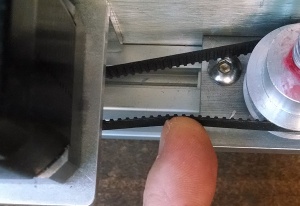
- Using the force guage press down on the top belt until it touches the bottom belt and record the measurement.
- Adjust the belt tension until the below readings are achieved.
Gigabot Regular X = 8.5 newtons, Y = 8.0 newtons
Gigabot XL and XLT X = 8.5 newtons, Y = 7.5 newtons


Belt Tension *Option 2
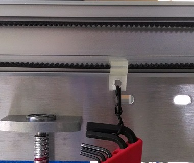
If the belts are too loose the accuracy and surface finish of your part will suffer. Belts too tight will cause accelerated wear and reduce the life of your machine. Using the belt tension clip, supplied allen wrench set and a piece of string to hang the allen wrench set on the belt. File:Belt clip.STL
- If the belt is too loose it will look like this below (EDIT: all wrenches should be inside red case in photo):

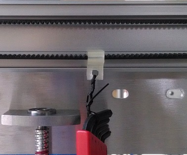
- If the belt has the proper tension it will look like this below:

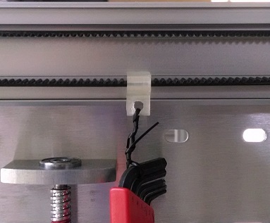
- If the belt is too tight it will look like this below:

- Setting the belt tension for the Z axis belts:

Wheel Tension
Ensure the proper V-groove wheel adjustment for smooth operation. If the wheels are too loose the accuracy and surface finish of your part will suffer. Wheels too tight will cause undue stress on the motors and belts and reduce the life of your machine.
X and Y axis Wheels
- Using the supplied 8mm combination wrench and allen wrench
- Tighten the M5 nut fixing the wheel
- Loosen M5 nut 1/4 turn
- Adjust wheel tension by rotating the eccentric wheel spacer in a clockwise direction (when facing the head of the M5 bolt)
- Wheel should be just touching the aluminum bearing surface
- Tighten the M5 nut fixing the wheel
- Check there is no gap between the wheel and the bearing surface
- Using a force gauge to ensure the trolley requires no more than 7 newtons to move.
- Using a force gauge to ensure the Bridge requires no more than 17 newtons to move.


Z axis Wheels
- The two wheels on the back of the bed side plates should be touching the Z axis uprights bearing surface.
- Use one hand to hold them against the bearing surface while adjusting the eccentric spacers on the front two wheels.
- Repeat for both the right and left sides.
Leveling the bed
For GB3+ owners, follow these instructions to level your bed. GB2 and GB3 owners may continue reading below.
This is a very important step! Getting the bed truly level will greatly benefit your printing experience as you see how important it is to have an even and consistent first layer in the printing process. The first layer of your print is the foundation of your object.
The entire leveling process for GB2 and GB3 has been documented in this video.
- Apply liberal amount of grease to the threaded rods that raise and lower the bed
- Loosen the (2) M5 x 12 screws 1/8 turn that fix the nut cup to the bed side plate. Both right and left sides.
- Loosen the (2) M5 x 12 screws 1/8 turn that fix the upper bearing block to the side plate. Both right and left sides.
- Check the right and left bed side plates are at the same height by measuring the distance between the top of the Z axis motor and the bed side plate.
- Using Pronterface to raise the bed halfway up
- Again check the wheel tension on the eight V-groove wheels
- Continue raising the bed to near the top of its travel
- Again check the tension of the eight V-groove wheels. If the wheels have become noticeably tighter or looser it indicates the Z axis uprights may not be exactly parallel. Using a precision square check the uprights form a true 90 degree angle to the lower base of the machine.
- Tighten the (2) M5 x 12 screws that fix the nut cup to the bed side plate. Both right and left sides.
- Tighten the (2) M5 x 12 screws that fix the upper bearing block to the side plate. Both right and left sides.
- Loosen the (2) M5 x 12 screws that fix the bed side plates to the bed support rails. Repeat for all four corners.
- Move the bed support rails to the top of the slot, tighten the M5 x 12 screw then loosen 1/4 turn. Repeat for all four corners.
Attaching dial indicator for GB3
Leveling the bed part two

- Use the supplied dial indicator and dial indicator block. Attach the dovetail mount to the dial indicator and tighten. Insert the cylindrical end of the dovetail mount into the dial indicator block and fix in place using the supplied M3 screw
- Place the dial indicator block over the head of the main extruder bolt and fix it into place using the second M3 screw.
- Swivel the dial indicator feeler arm to form an approximately 20 degree angle to the bed plate as viewed from the side.
- Ensure the dial indicator feeler arm is lower than the hot-end so that it contacts the bed surface before the hot-end.
- Place the print head near the center of the table and slowly raise the bed until it contacts the dial indicator, moving the needle approximately 0.010 inches (or approximately 90 degrees of needle movement).
 Bed Leveling
- Use your hand to push on the trolley plate (and not the extruder itself), move the print head near all four corners of the bed.
- Determine the lowest corner. Adjust the bed leveling nut on the underside of the bed to pull the three highest corners of the bed down to make the bed level.
- Repeat this procedure as necessary until the bed is level within 0.005" - 0.007".
- When the bed is level, finish tightening the (2) M5 x 12 screws that fix the bed side plates to the bed support rails. Repeat for all four corners and verify the leveling has not changed.
- Remove the dial indicator and return it to its case. Remove the screws from the indicator holder block and place all items into the indicator case.

Setting Z axis Home position
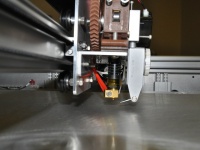
With the bed at the Z home position the gap between the hot-end nozzle and the top of the print surface should be 0.010 inches (about 3 sheets of standard paper). If the gap is too small, the hot-end nozzle will either contact the print surface or squish the first layer too much. If the gap is too large, the first layer of plastic will not stick to the print surface adequately.
To verify the Z home position is correct, measure the thickness of the first layer perimeter of your print, brim or skirt using a calipers or micrometer. The thickness should be the same as the first layer height as set in Slic3r or Simplify3D.
- For GB2, adjust the Z home position using the Z axis limit switch screw found on the right rear corner of the bed frame. For GB3, the screw is located on the right front corner of the bed frame.
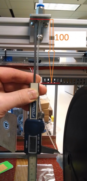
- Ensure the M5 x 65 screw (M5 x 70 for GB3) is inserted into the Z axis limit switch block with the head sticking up about 50mm above the block and the lock nut (GB2 only) is tightened
- Position the extruder and hot-end at the rear of it's travel (Max Y position)
- When homing the Z-axis, ensure the hot-end does not come into contact with the bed -- manually move the print head to the very front or back of the machine so that the nozzles are not above the bed. You can also manually stop the bed motion by triggering the Z axis limit switch with your finger.
- Using the Pronterface control panel or the Viki, press the Home Z axis button
- Adjusting the M5 x 65 (M5 x 70 for GB3) screw down will to raise the bed higher and raising the screw will lower the home position. Ensure the lock nut (GB2 only) is tightened after adjusting the limit switch screw.
- One revolution of the screw will change the bed height 0.8mm (0.031")
- Use a 0.010" feeler gauge or 3 sheets of paper to gauge the distance between the nozzle and the bed. Keep adjusted the screw and homing Z until there is slight friction on the feeler gauge or paper between the bed and nozzle.

For GB3, the screw is located at the front right corner of the bed frame

Calibrating the filament feed
Correct extrusion quantity is important for quality prints. If the extruder is pushing too much plastic layers will overfill resulting in bumpy and uneven surfaces. Extruding too little plastic will cause weak bonds and gaps between layers resulting in a weak structure.
- Connect Gigabot's USB cable to your computer
- Turn on Gigabot
- Open Pronterface
- Click on <Connect> button at the top of the screen

Read the current extruder calibration number in Pronterface
- Pronterface will display:
- Connecting...
- start
- Printer is now online.
- ...
- echo: M92 X118.52 Y118.52 Z4031.50 E1000.00
- ...
- Check that filament is installed in extruder
- Turn on hot-end fan
- Heat hot-end to 210C
- When hot-end is up to temperature extrude 10mm of filament at 100mm/sec until you see filament coming out of the hot-end
- Mark the filament 100mm from rear filament tube shelf
- Extrude 80mm of filament using Pronterface
- Measure actual extrusion distance
- Perform calculation:
- (Commanded distance x old calibration number) / actual extrusion distance = new calibration number
- (80 x 1000) / 83.5 = 958
In Pronterface:
- Type “M92 E958” <enter>
- Type “G92 E0” <enter>
- Repeat the steps above to verify the extruder moves exactly 80mm when commanded.
Save the new extruder calibration (M92 Exxxx)
- Type M500 to save the calibration to the permanent memory.
- Simplify3D-> FFF Settings -> Scripts -> Starting G-code (M92 E958 ; calibrate E)
Dual Extrusion Settings
Firmware 4.1.5 and above (Azteeg X3-PRO control board)
- Simplify3D .factory file for 4.1.5
- 0.4 Left 0.4 Right Dual extruder calibration
- 0.4 Left 0.8 Right Dual extruder calibration
- 0.8 Left 0.8 Right Dual extruder calibration
Firmware 4.1.3 and below (Azteeg X3 control board)
- Simplify3D .factory file for 4.1.3
- 0.4 Left 04 Right Dual extruder calibration
Exact distance between the extruders must be set in either the firmware (firmware 4.1.5) or in Simplify3D (firmware 4.1.3).
By default the distance from the center line of E0 to E1 is set as:
X = -55mm Y = 0mm
The exact distance can be found by performing a test print using the above .factory file to print a 40mm box.
The first 10mm of height will be with the left extruder and the second 10mm of height with the right extruder.
Measuring any offset and then adjusting the above offset values using the Viki controller interface (4.1.5) or Simplify3D (4.1.3)


Firmware 4.1.5
- Measure the offset (if any) between the first and second 10mm of height in both the X and Y axis.
- Adjusting the offset in the Viki controller:
- Press center button of the Viki
- Scroll down and select “Control”
- Scroll down and select “Motion”
- Scroll down and select “T1X”
- If the top 10mm was shifted to the right (+X direction) then increase the value by the amount of the shift and click the center button
- Scroll up and select the “up one level icon”
- Scroll down and select “T1Y”
- If the top 10mm was shifted to the back(+Y direction) then increase the value by the amount of the shift and click the center button
- Scroll up and select the “up one level icon”
- Scroll down and select “Store Memory” two times.
- Turn off power and turn on power.
- Check the T1X and T1Y values are changed
- Run the above gcode file and verify there is no shift between the bottom 10mm and the top 10mm
Firmware 4.1.3
- Measure the offset (if any) between the first and second 10mm of height in both the X and Y axis.
- Adjust the "Toolhead offsets" for tool 1 under the G-Code tab in the .fff settings.

Additional Resources
- Video guide to calibrating the extrusion: https://www.youtube.com/watch?v=YUPfBJz3I6Y
- Additional calibration guides on the web: http://reprap.org/wiki/Triffid_Hunter%27s_Calibration_Guide http://richrap.blogspot.com/2012/01/slic3r-is-:nicer-part-1-settings-and.html
[Dozuki assembly guide] NOTE: Link available for legacy Gigabots only--do not use Dozuki instructions to assemble a new Gigabot!