Calibrating your Gigabot
Contents
Calibrating your Gigabot
Correct calibration will ensure the machine moves freely and in a precise manner. Investing some time with the calibration and your print quality will improve.
If you received a fully assembled Gigabot skip to "Leveling the bed part two" below
Belt Tension
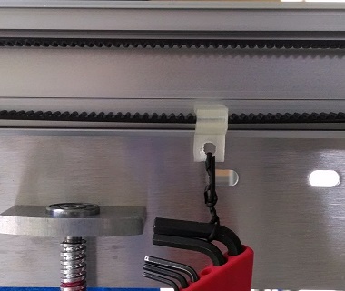
Ensure the proper belt tension for the two Y axis belts and the one X axis belt. If the belts are too loose the accuracy and surface finish of your part will suffer. Belts too tight will cause accelerated wear and reduce the life of your machine. Using the belt tension clip, supplied allen wrench set and a piece of string to hang the allen wrench set on the belt. File:Belt clip.STL Belt Clip
- If the belt is too loose it will look like this below:

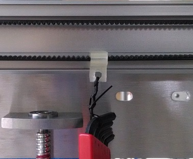
- If the belt has the proper tension it will look like this below:

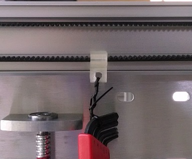
- If the belt is too tight it will look like this below:

Setting the belt tension for the Z axis belts:

Wheel Tension
Ensure the proper V-groove wheel adjustment for smooth operation. If the wheels are too loose the accuracy and surface finish of your part will suffer. Wheels too tight will cause undue stress on the motors and belts and reduce the life of your machine.
X and Y axis Wheels
- Using the supplied 8mm combination wrench and allen wrench
- Tighten the M5 nut fixing the wheel
- Loosen M5 nut 1/4 turn
- Adjust wheel tension by rotating the eccentric wheel spacer in a clockwise direction (when facing the head of the M5 bolt)
- Wheel should be just touching the aluminum bearing surface
- Tighten the M5 nut fixing the wheel
- Check there is no gap between the wheel and the bearing surface
- Check that wheel is not too tight and you can spin the wheel by hand
Z axis Wheels
- The two wheels on the back of the bed side plates should be touching the Z axis uprights bearing surface.
- Use one hand to hold them against the bearing surface while adjusting the eccentric spacers on the front two wheels.
- Repeat for both the right and left sides.
Leveling the bed
This is a very important step! Getting the bed truly level will greatly benefit your printing experience as you see how important it is to have an even and consistent first layer in the printing process. The first layer of your print is the foundation of your object.
- Apply liberal amount of grease to the threaded rods that raise and lower the bed
- Loosen the (2) M5 x 12 screws 1/8 turn that fix the nut cup to the bed side plate. Both right and left sides.
- Loosen the (2) M5 x 12 screws 1/8 turn that fix the upper bearing block to the side plate. Both right and left sides.
- Check the right and left bed side plates are at the same height by measuring the distance between the top of the Z axis motor and the bed side plate.
- Using Pronterface to raise the bed halfway up
- Again check the wheel tension on the eight V-groove wheels
- Continue raising the bed to near the top of its travel
- Again check the tension of the eight V-groove wheels. If the wheels have become noticeably tighter or looser it indicates the Z axis uprights may not be exactly parallel. Using a precision square check the uprights form a true 90 degree angle to the lower base of the machine.
- Tighten the (2) M5 x 12 screws that fix the nut cup to the bed side plate. Both right and left sides.
- Tighten the (2) M5 x 12 screws that fix the upper bearing block to the side plate. Both right and left sides.
- Loosen the (2) M5 x 12 screws that fix the bed side plates to the bed support rails. Repeat for all four corners.
- Move the bed support rails to the top of the slot, tighten the M5 x 12 screw then loosen 1/4 turn. Repeat for all four corners.
Leveling the bed part two

- Use the supplied dial indicator and dial indicator block. Attach the dovetail mount to the dial indicator and tighten. Insert the cylindrical end of the dovetail mount into the dial indicator block and fix in place using the supplied M3 screw
- Place the dial indicator block over the head of the main extruder bolt and fix it into place using the second M3 screw.
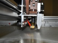
- Swivel the dial indicator feeler arm to form an approximately 20 degree angle to the bed plate as viewed from the side.
- Ensure the dial indicator feeler arm is lower than the hot-end so that it contacts the bed surface before the hot-end.
- Place the print head near the center of the table and slowly raise the bed until it contacts the dial indicator, moving the needle approximately 0.010 inches (or approximately 90 degrees of needle movement).
 Bed Leveling
- Use your hand to push on the trolley plate (and not the extruder itself), move the print head near all four corners of the bed.
- Determine the lowest corner. Adjust the bed leveling nut on the underside of the bed to pull the three highest corners of the bed down to make the bed level.
- Repeat this procedure as necessary until the bed is level within 0.005" - 0.007".
- When the bed is level, finish tightening the (2) M5 x 12 screws that fix the bed side plates to the bed support rails. Repeat for all four corners and verify the leveling has not changed.
- Remove the dial indicator and return it to its case. Remove the screws from the indicator holder block and place all items into the indicator case.

Setting Z axis Home position
With the bed at the Z home position the gap between the hot-end nozzle and the top of the print surface should be zero. If the gap is too small the hot-end nozzle will contact the print surface and if the gap is too large the first layer of plastic will not stick to the print surface.
To verify the Z home position is correct measure the thickness of the first layer perimeter of your print, brim or skirt using a calipers or micrometer. The thickness should be the same as the first layer height as set in Slic3r or Simplify3D.
- Adjust the Z home position using the Z axis limit switch screw found on the right rear corner of the bed frame
- Ensure the M5 x 65 screw is inserted into the Z axis limit switch block with the head sticking up about 50mm above the block and the lock nut is tightened
- Position the extruder and hot-end at the rear of it's travel (Max Y position)
- When homing the Z axis ensure the hot-end does not come into contact with the bed. You can manually stop the bed motion by triggering the Z axis limit switch with your finger.
- Using the Pronterface control panel press the Home Z axis button
- Adjusting the M5 x 65 screw down will to raise the bed higher and raising the screw will lower the home position. Ensure the lock nut is tightened after adjusting the limit switch screw.
- One revolution of the screw will change the bed height 0.8mm

Calibrating the filament feed
Tuning the feed rate of the extruder is important to obtaining the the correct amount of plastic flow. If you extrude too much plastic the layers will overfill and cause a bumpy and uneven surface. Extruding too little plastic will cause weak bonds and gaps between layers and a weak structure.
- Here is a great video guide to calibrating the extrusion: https://www.youtube.com/watch?v=YUPfBJz3I6Y
- Once you have calculated the new extruder calibration number (M92 Exxxx) you can enter it into
- Simplify3D-> FFF Settings -> Scripts -> Starting G-code (M92 E1850 ; calibrate E)
- or
- Slicer-> Printer Settings -> Custom G-code -> Start G-code (M92 E1850 ; calibrate E)
- Simplify3D-> FFF Settings -> Scripts -> Starting G-code (M92 E1850 ; calibrate E)
There are a number of great calibration guides on the web including: http://reprap.org/wiki/Triffid_Hunter%27s_Calibration_Guide http://richrap.blogspot.com/2012/01/slic3r-is-nicer-part-1-settings-and.html
After you have done the rough calibration of the filament feed you can print a hollow test square with a single wall perimeter. Measure the perimeter thickness and compare that to what Slic3r expects it to be (stated near the top of the g-code file). The extrusion width can be adjusted under Slicer -> filament settings -> Extrusion multiplier.